
Department Lab Facilities
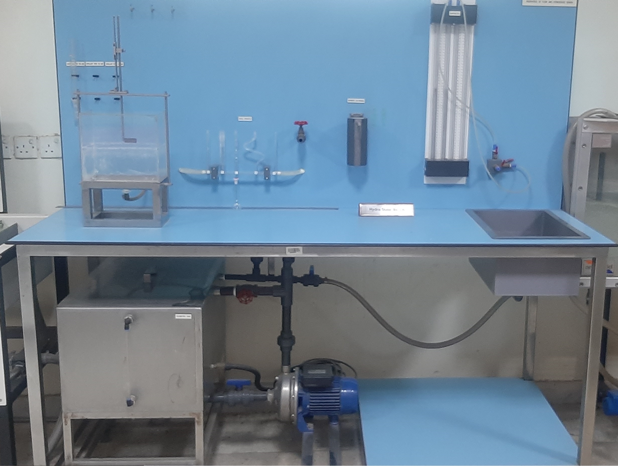
Fluid Properties & Hydrostatic
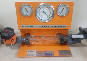
Cavitation Demonstration

Pipes Surge & water Hammer Apparatus
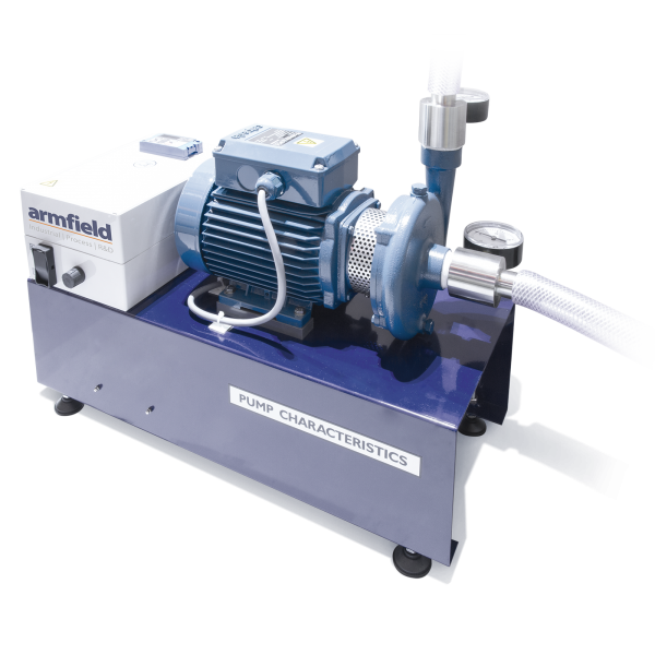
Centrifugal Pump Characteristics
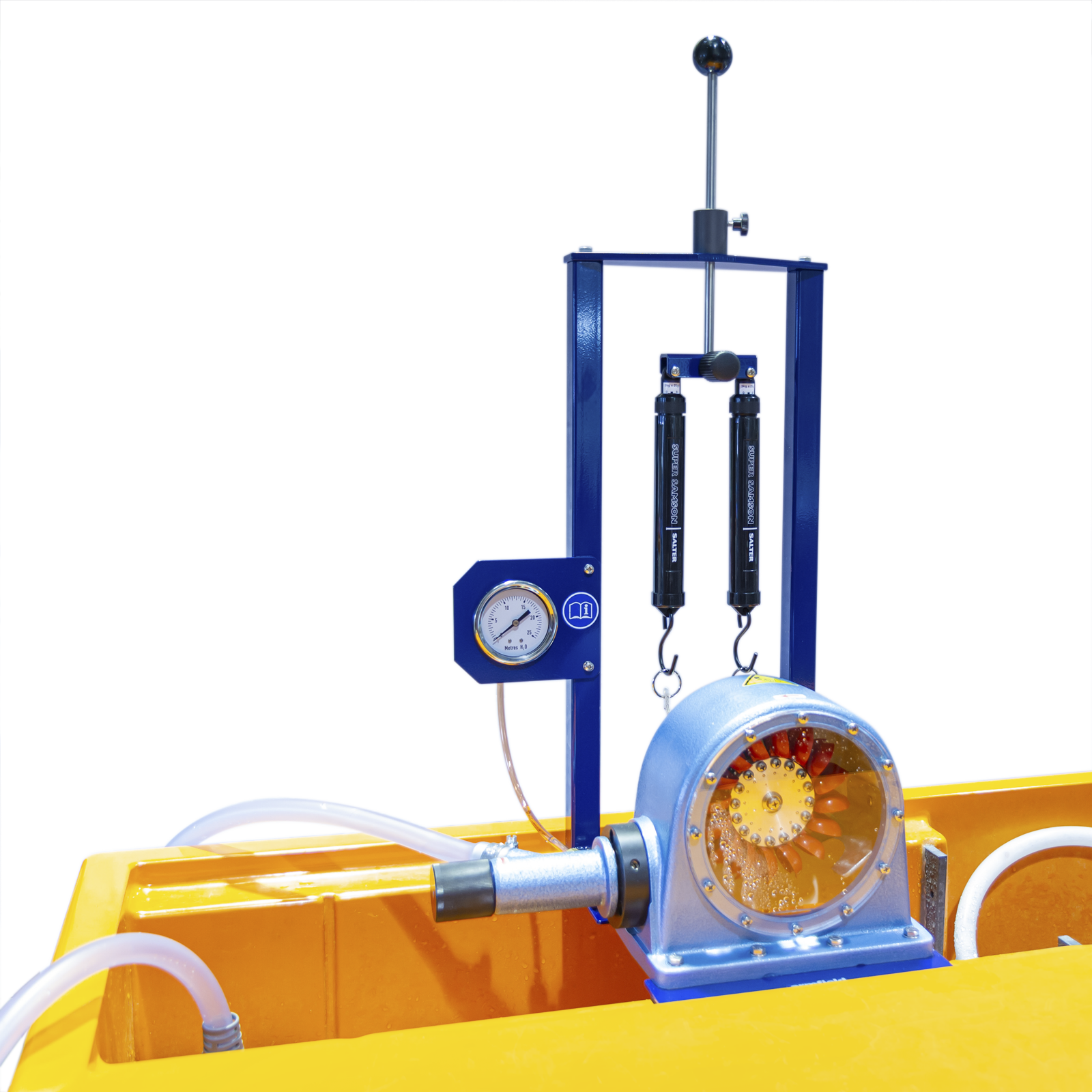
Demonstration Pelton Turbine
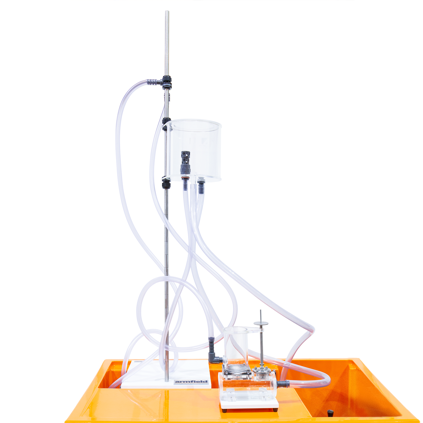
Hydraulic Ram
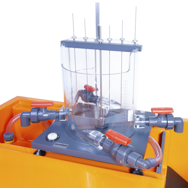
Free & Forced Vortices
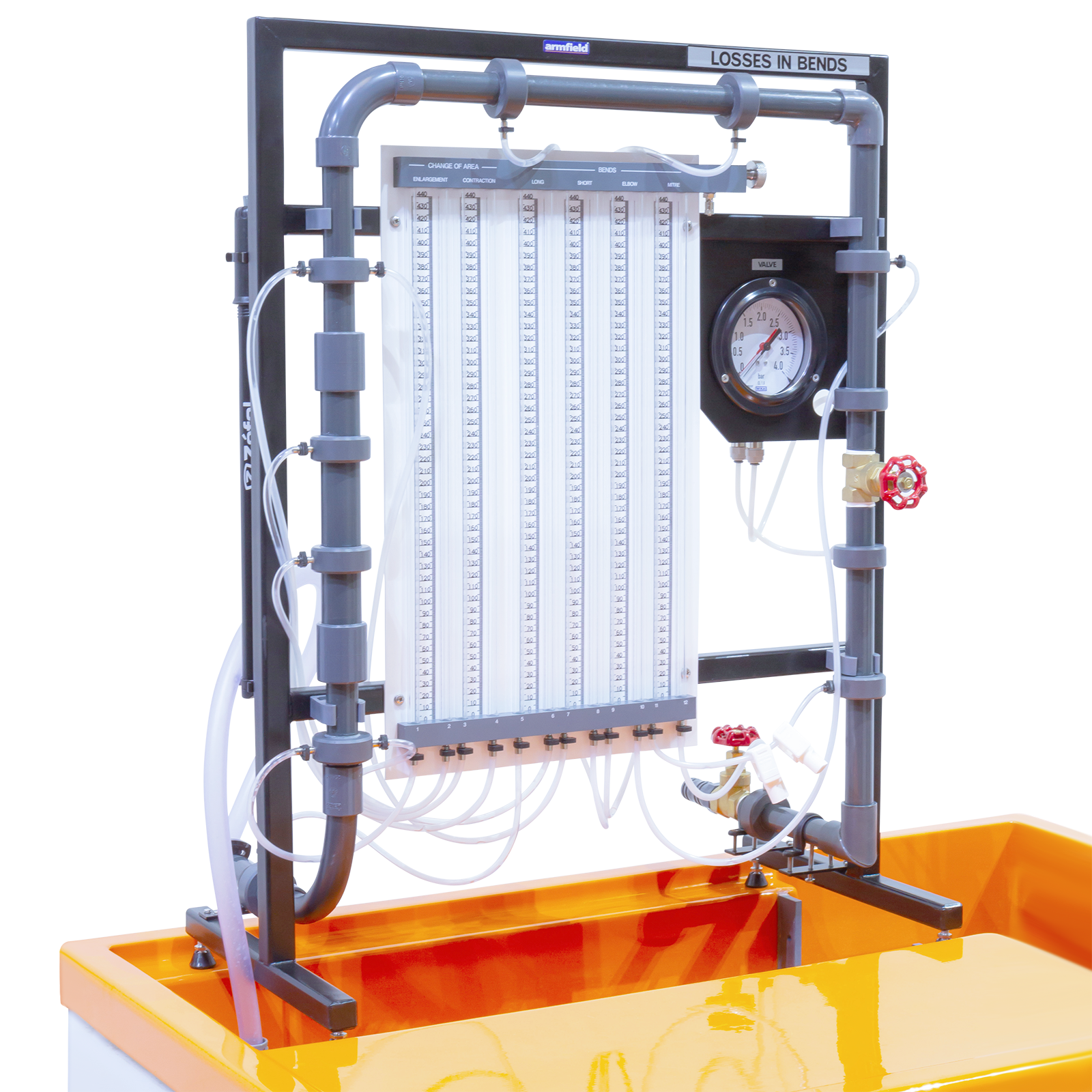
Energy losses in bends
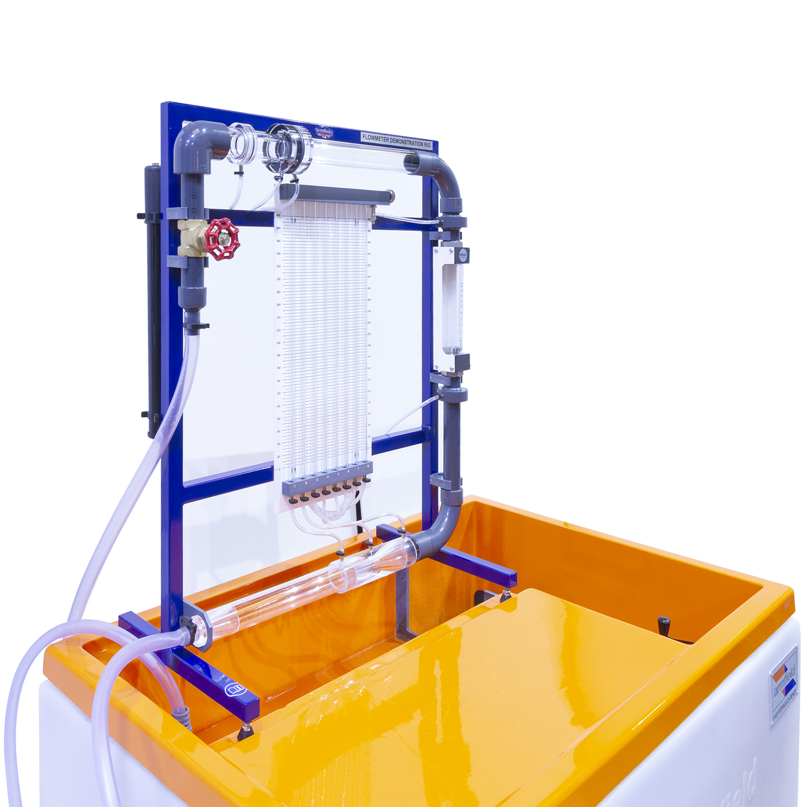
Flow meter Demonstration
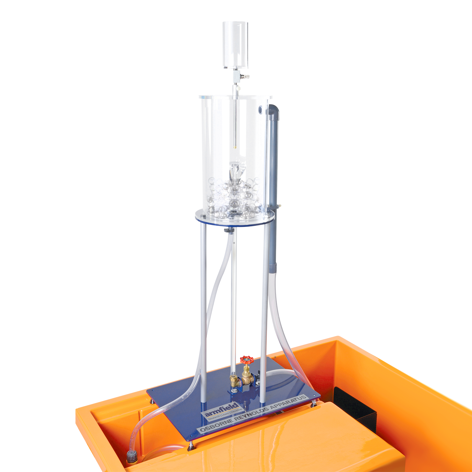
Osborne Reynold’s Demonstration
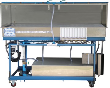
Basic Hydrology Apparatus
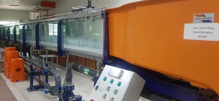
Laboratory Flow Channel
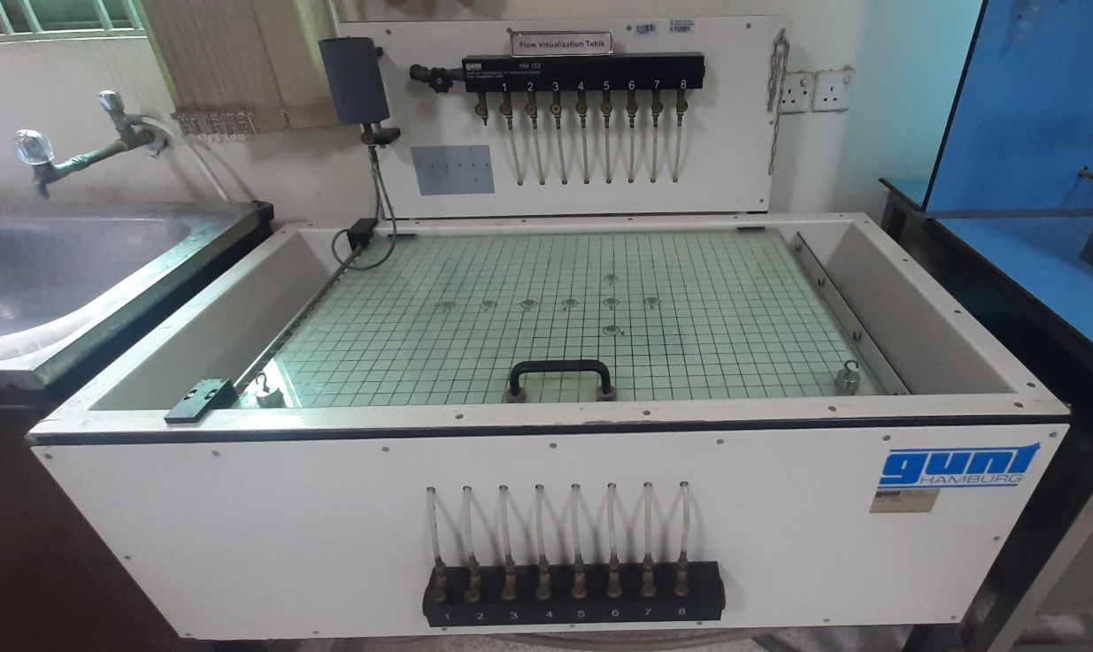
Flow Visualisation Table
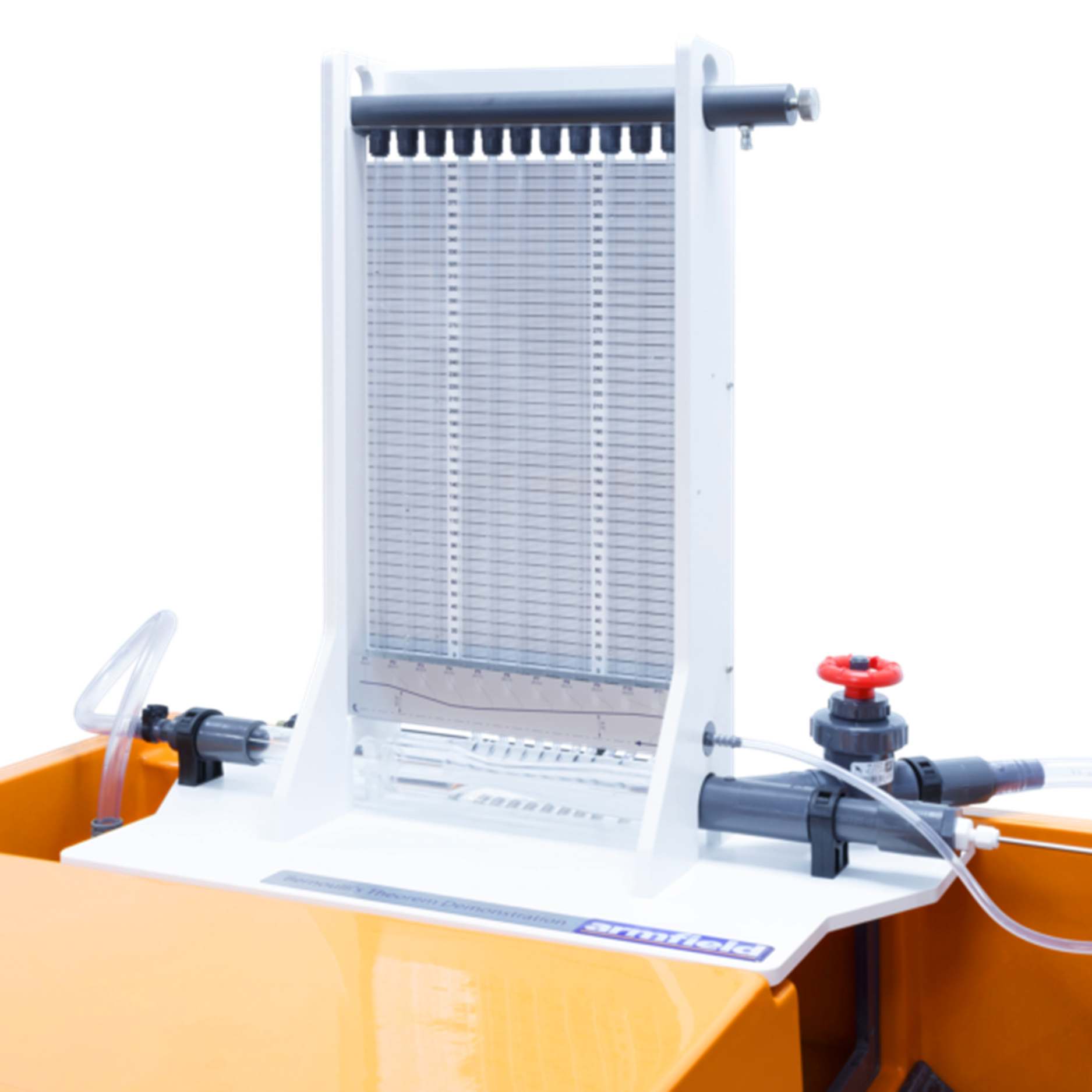
Bernoulli’s Theorem Demonstration